Technology explained · 3D reconstruction
From Photos to Novel Views: Understanding 3D Gaussian Splatting
Gaussian splatting turns observations of a scene into a 3D representation that can be rendered from new viewpoints. MakeWorlds brings image input, reconstruction, inspection, and scene preparation into one workflow. This article connects the camera geometry, scene representation, and rendering principles behind that process.

A reconstructed scene gives the viewer control over where to look from. Moving around an object or approaching furniture inside a room changes the relationship between foreground and background. That makes it possible to inspect appearance and layout together when recording or presenting a space.
The MakeWorlds Train and indoor case studies show paired photographs and renders, letting readers inspect contours and textures directly. Three connected stages explain how such results are produced: recovering camera relationships, representing the scene, and rendering a chosen view.
Recover camera and scene relationships from multiple views
Photographs from different positions provide complementary projections. Shared corners and texture establish correspondences that connect the images.
Structure from Motion, or SfM, uses those correspondences to estimate camera poses and an initial set of 3D points. They provide the spatial reference for reconstruction.
Capture from changing positions with overlap between adjacent views. Build connected coverage first, then add closer views of important details.
The estimated cameras allow a scene representation to be refined against known observations and rendered from specified viewpoints.
Represent appearance with spatial Gaussian primitives
3DGS represents a scene with many spatial Gaussians. Each carries position, scale, orientation, opacity, and appearance information; their combined contributions form the scene’s image.
A Gaussian’s influence falls away from its center. A soft ellipsoid is a useful illustration: its projection contributes a footprint that fades toward the edges.
The renderer blends these projected contributions using their depth order and opacity. The animation below uses a cup to illustrate projection and image formation.
Training compares rendered training views with their photographs and adjusts the representation to fit multiple observations.
Render a new position, with new parallax and occlusion
A changed camera position or orientation changes projected positions, sizes, and occlusion. Rendering from that camera produces a new view of the same spatial representation.
With sideways camera motion, foreground and background shift by different amounts. A line of sight may also pass an obstruction and reveal something behind it. The plan-view diagram illustrates that relationship.
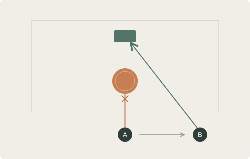
A single panorama provides directional views around one capture position. A reconstructed scene also supports changing that position, giving capture planning and presentation routes another dimension to work with.
Plan capture and review around the intended use
Define the main viewing areas, intended camera route, and details that need close inspection before capture. Connected coverage, sharp photographs, and reasonably stable lighting provide useful observations; closer views add evidence for important textures and structures.
Review contours, occlusion changes, and newly visible regions along the planned route. Give reflective surfaces, glass, low-texture areas, and moving objects particular attention when deciding where to recapture or refine. Areas not observed in the source material still require additional evidence.
This article explains image reconstruction and view rendering. Measurement, collision handling, and engineering analysis require suitable geometric data and validation for their intended use.
Connect source images, scenes, and evaluation in MakeWorlds
MakeWorlds Studio organizes image input, reconstruction, inspection, and scene preparation into a connected workflow. Users work from captured material to a reconstructed scene, inspect it from different positions, and prepare it for their presentation goals.
The published cases provide concrete examples: Train pairs locomotive detail with three-platform results; the indoor study examines cabinetry, repeated patterns, and bookshelf contents. Matched images and full test-set metrics let readers check which structures and visual details the reconstructions retain.